
Blueprint Symbols Meaning: Precision in Florida Projects
Most American construction errors start with a single misread symbol, costing teams thousands in Florida project delays. Blueprint symbols are more than just marks on paper. They are the foundation for safe builds and code compliance in residential and commercial work. This guide delivers clear insight into blueprint symbol meanings, helping contractors and architects avoid costly mistakes and strengthen every phase of their projects.
Table of Contents
- What Blueprint Symbols Mean In Engineering
- Core Categories Of Blueprint Symbols Explained
- Key MEP Symbols: HVAC, Electrical, Plumbing
- Decoding Symbols For Accurate Site Plans
- Risks Of Misreading Blueprint Symbols
Key Takeaways
| Point | Details |
|---|---|
| Standardization of Symbols | Blueprint symbols follow international standards, ensuring clear communication across projects and disciplines. |
| Risk of Misinterpretation | Misreading symbols can lead to structural issues, safety violations, and financial penalties. |
| Discipline-Specific Symbols | Different engineering fields have unique symbols, highlighting the importance of tailored reference guides. |
| Importance of Reference Guides | Maintaining updated symbol guides helps prevent misunderstandings and ensures project compliance. |
What Blueprint Symbols Mean in Engineering
Blueprint symbols represent a universal language of communication for engineers, architects, and construction professionals. These standardized graphical representations convey critical technical details about design specifications, material requirements, and structural components. Engineering drawing symbols are governed by international standards like ISO 128 and ASME Y14.38, ensuring consistent interpretation across different projects and regions.
In Florida construction and engineering contexts, these symbols serve as precise communication tools that eliminate ambiguity and potential misunderstandings. Each symbol represents specific technical information ranging from wall thicknesses and material types to electrical connections and plumbing configurations. Professional engineers and contractors must interpret these symbols accurately to ensure project compliance, safety, and structural integrity.
The complexity of blueprint symbols varies depending on the discipline. Architectural symbols differ from mechanical engineering symbols, which in turn vary from electrical or structural engineering notations. Common categories include line types (continuous, dashed, dotted), geometric shapes representing specific components, and standardized abbreviations that communicate dimensions, materials, and technical specifications with remarkable precision.
Pro tip: Always maintain an updated blueprint symbol reference guide specific to your engineering discipline to ensure accurate interpretation and prevent costly misunderstandings during project implementation.
Core Categories of Blueprint Symbols Explained
Blueprint symbols are categorized into specialized groups that enable precise technical communication across different engineering disciplines. Architectural drawing symbols encompass critical visual representations that include essential building elements like walls, doors, windows, and spatial configurations. These graphical notations provide engineers and architects with a standardized method of communicating complex design intentions through universally recognized visual language.
The primary categories of blueprint symbols extend beyond architectural representations to include mechanical, electrical, and plumbing (MEP) symbols. Mechanical symbols detail equipment placement, ventilation systems, and structural support mechanisms. Electrical symbols illustrate wiring configurations, outlet locations, and power distribution networks. Plumbing symbols communicate pipe routing, fixture placements, and drainage system specifications, ensuring comprehensive technical documentation for construction professionals.
Each symbol category serves a specific communication purpose in Florida construction projects. Architectural symbols define spatial relationships and building geometry, while specialized symbols like reflected ceiling plan notations provide additional layers of technical detail. Structural engineering symbols represent load-bearing elements, material specifications, and critical connection points that ensure building integrity and compliance with local building codes.
Here’s a summary comparing the main categories of blueprint symbols and their primary functions:
| Symbol Category | Main Function | Typical Elements |
|---|---|---|
| Architectural | Define spaces and geometric layout | Walls, doors, windows |
| Structural | Indicate load-bearing and support details | Beams, columns, foundations |
| Mechanical | Show equipment placement and HVAC systems | Ducts, fans, equipment |
| Electrical | Detail wiring and power layouts | Outlets, panels, lighting |
| Plumbing | Map water and waste systems | Pipes, valves, fixtures |
Pro tip: Invest in a comprehensive blueprint symbol reference guide that covers multiple engineering disciplines to enhance your ability to interpret complex technical drawings accurately.
Key MEP Symbols: HVAC, Electrical, Plumbing
Mechanical, Electrical, and Plumbing (MEP) blueprint symbols represent the complex infrastructure that brings buildings to life in Florida construction projects. MEP blueprint symbols are intricate visual languages that communicate critical system details through standardized graphical representations. These symbols enable precise communication among engineers, contractors, and inspectors by depicting the exact placement and specifications of building systems.
HVAC symbols provide detailed information about heating, ventilation, and air conditioning components. These specialized notations include representations for supply and return air ducts, fans, diffusers, thermostats, and equipment locations. Electrical symbols are equally complex, documenting circuit breakers, outlet types, lighting fixtures, panel boards, and wiring configurations. Plumbing symbols communicate pipe routing, diameter, material, valves, fixture types, and drainage system specifications, ensuring comprehensive understanding of a building’s water and waste management infrastructure.

In Florida’s diverse construction environment, understanding these MEP symbols is crucial for project success. The symbols not only guide installation but also help professionals identify potential system conflicts, plan maintenance strategies, and ensure compliance with local building codes. Experienced contractors recognize that these intricate symbols serve as a blueprint’s technical roadmap, revealing how different building systems interact and integrate within the overall architectural design.
Pro tip: Develop a comprehensive personal reference guide of MEP symbols specific to your engineering discipline to quickly interpret complex technical drawings and minimize potential misunderstandings during project implementation.
Decoding Symbols for Accurate Site Plans
Site plan accuracy depends on understanding a complex language of graphical representations that communicate critical spatial and infrastructural details. Site plan symbols are essential technical communication tools that translate complex design intentions into precise visual information. These symbols include critical elements like north arrows for orientation, property boundaries, topographical contours, utility markings, and landscape features that guide construction professionals through intricate site development processes.
Each symbol on a site plan serves a specific purpose in representing physical and infrastructural characteristics. Topographical symbols demonstrate ground elevation changes through contour lines, revealing slope gradients and potential drainage patterns. Utility symbols document underground and surface infrastructure like water lines, electrical conduits, sewage systems, and communication networks. Boundary markers precisely define property lines, setbacks, and easement restrictions, providing legal and physical context for construction activities.
In Florida’s diverse landscape, site plan symbols become even more critical due to unique environmental challenges such as flood zones, coastal regulations, and complex terrain variations. Professional engineers and surveyors use these symbols to communicate nuanced site conditions that impact structural design, foundation requirements, and environmental compliance. Accurate symbol interpretation helps prevent costly mistakes, ensures regulatory adherence, and facilitates seamless communication among architects, contractors, municipal inspectors, and property owners.
Pro tip: Develop a comprehensive personal reference guide of site plan symbols, categorizing them by type and function, to quickly interpret complex technical drawings and minimize potential misunderstandings during project planning.
Risks of Misreading Blueprint Symbols
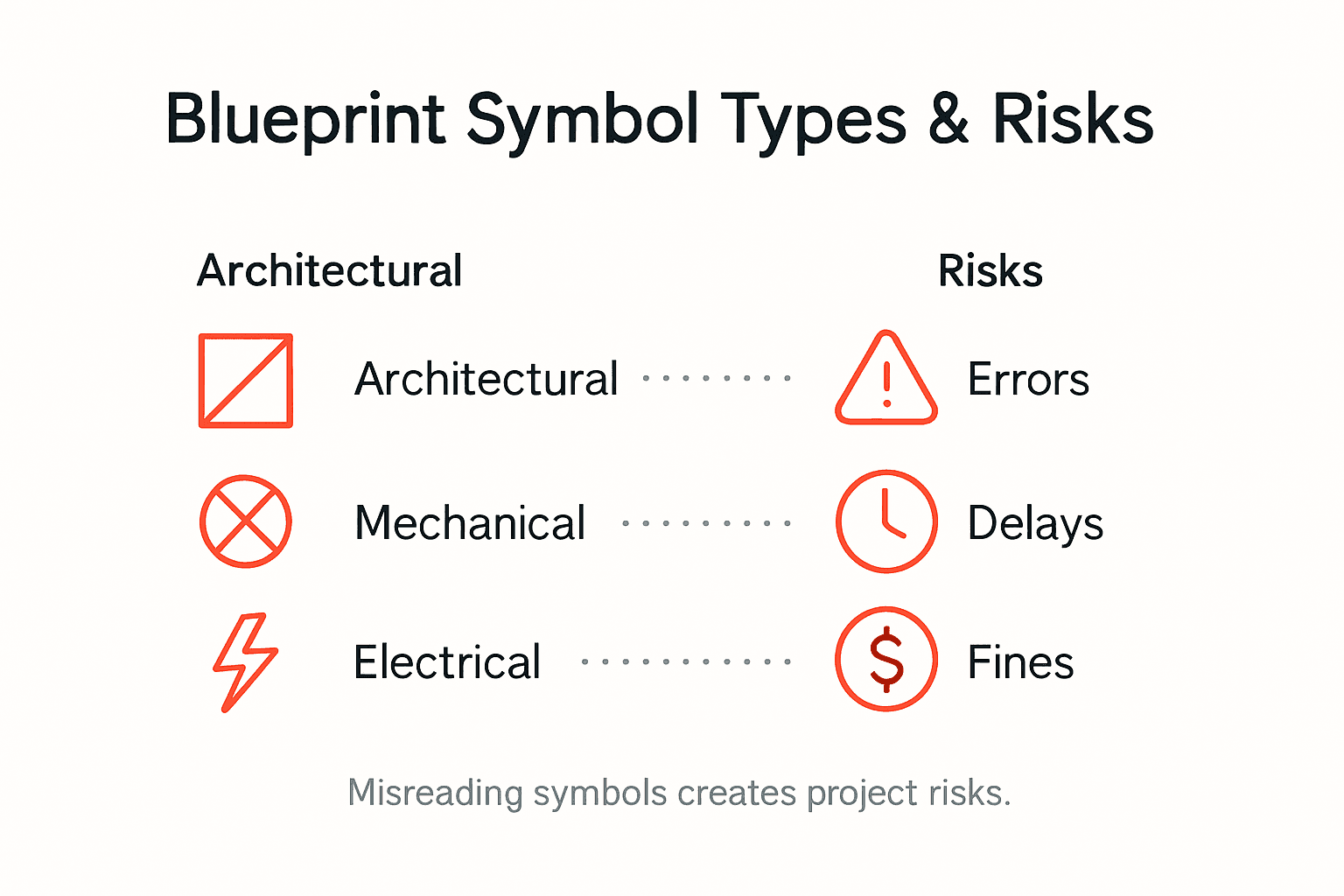
Blueprint symbol misinterpretation represents a critical vulnerability in construction and engineering projects, potentially leading to significant financial and safety consequences. Construction errors stemming from blueprint misreadings can result in substantial material waste, project delays, and potentially dangerous structural compromises. These misunderstandings transform seemingly minor symbol confusion into major operational risks that extend far beyond simple drawing inaccuracies.
The potential risks of misreading blueprint symbols manifest across multiple dimensions of project execution. Structural engineering mistakes can compromise building integrity, with incorrect interpretation of load-bearing symbols potentially leading to foundation weaknesses or inappropriate support configurations. Mechanical and electrical symbol errors might create dangerous installation scenarios, such as improper wiring connections or inappropriate equipment placement that violate safety codes and regulations.
In Florida’s complex regulatory environment, blueprint symbol misreadings carry additional legal and financial implications. Local building codes, environmental restrictions, and specific regional construction requirements mean that even minor symbolic misunderstandings can trigger compliance violations. Professional engineers and contractors face potential legal liabilities, project shutdowns, mandatory reconstructions, and significant financial penalties when blueprint symbols are incorrectly interpreted or implemented.
This table outlines the risks of blueprint symbol misinterpretation in construction:
| Risk Type | Example Outcome | Prevention Method |
|---|---|---|
| Structural | Foundation weakness | Professional training |
| Electrical | Unsafe wiring connections | Updated symbol guides |
| Compliance | Legal penalties | Regular code review |
| Financial | Material waste | Team skill assessments |
Pro tip: Invest in regular professional training and maintain updated symbol reference guides to ensure your team’s blueprint interpretation skills remain current and precise.
Mastering Blueprint Symbols for Flawless Florida Projects
Understanding the precise meaning behind every blueprint symbol is critical to avoiding costly errors and ensuring your Florida construction project meets all safety and compliance standards. From architectural layouts to complex MEP systems, misreading these symbols can cause delays, legal problems, or structural risks. Our expert engineering services specialize in interpreting and applying these symbols accurately across residential and commercial projects. We offer comprehensive support including inspections, permitting expeditor services, and detailed blueprint analysis to guide your project smoothly from concept to completion.

Ready to eliminate uncertainty and guarantee precision in your next project? Visit Florida Licensed Engineers for trusted expertise in architectural, structural, mechanical, electrical, and plumbing plans. Enhance your confidence with our civil engineering services addressing drainage, grading, utility layouts, and flood mitigation. Do not let blueprint symbol confusion threaten your project timeline or budget. Contact us today to ensure your engineering plans are flawless and compliant.
Frequently Asked Questions
What are the main categories of blueprint symbols?
The main categories of blueprint symbols include architectural, structural, mechanical, electrical, and plumbing symbols, each serving a specific function in conveying technical information about a project.
Why is it important to understand blueprint symbols in construction?
Understanding blueprint symbols is crucial for accurate communication among engineers and contractors, ensuring project compliance, safety, and the structural integrity of constructions.
What are the risks associated with misreading blueprint symbols?
Misreading blueprint symbols can lead to serious issues such as structural weaknesses, unsafe wiring connections, legal penalties for compliance violations, and significant financial losses due to material waste and project delays.
How can professionals ensure accurate interpretation of blueprint symbols?
Professionals can ensure accurate interpretation of blueprint symbols by maintaining updated reference guides, investing in regular training, and organizing team skill assessments to improve their reading and understanding of technical drawings.
Recommended
- 7 Essential Types of Architectural Blueprints Explained – FloridaLicensedEngineers.com
- How to Read Blueprints for Your Project Success – FloridaLicensedEngineers.com
- Architectural Plan Essentials: Ensuring Code Compliance – FloridaLicensedEngineers.com
- Complete Guide to the Role of Blueprints – FloridaLicensedEngineers.com
